Renewable Energy System Designs

Comprehensive portfolio of sustainable energy solutions

☀️ Activity 1: Rooftop Solar PV System (5 kW)

Rooftop Solar PV System Diagram showing Solar Panels, Hybrid Inverter, Battery Pack, and Electrical Appliances connected to Utility Grid
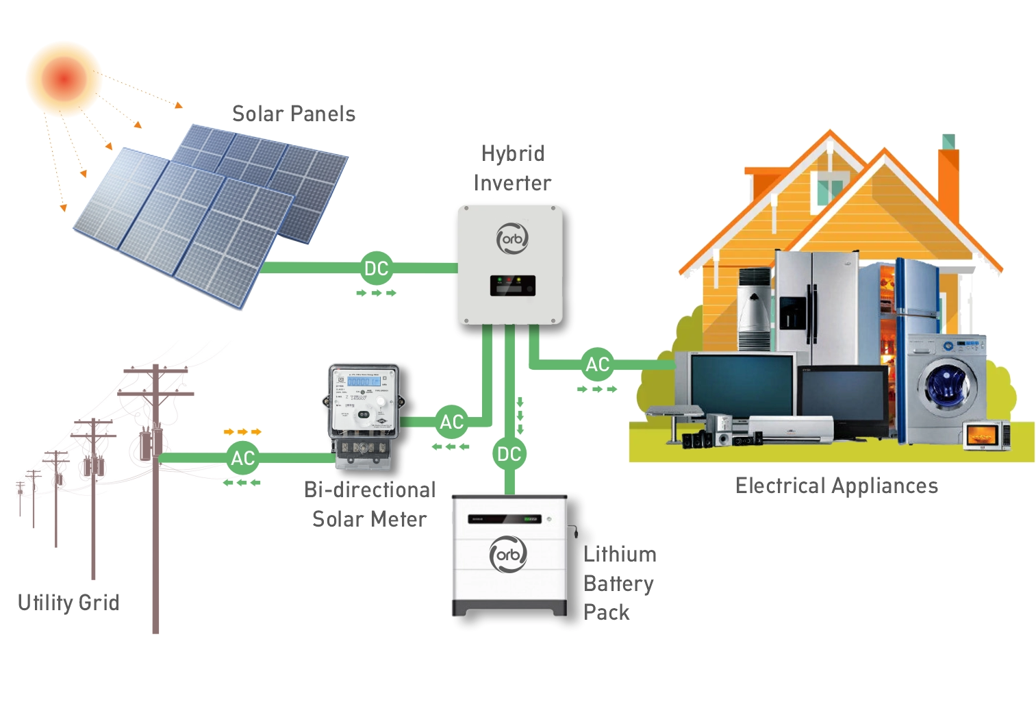
Source of energy: Solar irradiance captured by rooftop PV modules sized for 5 kW installed capacity. The panels convert incoming solar photons directly into DC electricity through the photovoltaic effect. This source is intermittent, peaking around noon, which necessitates storage.
Conversion process: The raw DC power is first fed through an MPPT (Maximum Power Point Tracking) charge controller to optimize energy harvest regardless of cloud cover or temperature. The optimized DC is then converted into grid-compatible AC power by a hybrid inverter. A BMS (Battery Management System)-regulated lithium-ion battery bank stores any surplus energy, ensuring power availability for night-time operation and during grid outages.
Output / utilization: The system intelligently directs the AC output to three destinations: supplying immediate home loads (appliances, lighting), prioritizing battery charging, and finally exporting excess electricity to the utility grid under a net metering agreement. System protection is comprehensive, including rapid shutdown devices, fuses, surge protectors, and manual isolators for fire and electrical safety.
Real-world relevance: Rooftop PV dramatically lowers utility bills and reduces the homeowner's carbon footprint, promoting decentralized energy production. It creates local jobs in installation and maintenance. By integrating digital monitoring (IoT), the system achieves smart-grid compatibility, enabling predictive maintenance, fault detection, and real-time energy optimization across urban and suburban homes.

🌬️ Activity 2: Hybrid Solar–Wind System for Rural Health Clinic

Hybrid Solar-Wind System Diagram showing Wind Turbines, PV Array, Controllers, Battery Bank, Inverter, and AC Load
Source of energy: The system draws energy from two complementary sources: solar energy from PV panels during the day, and wind energy from a small-scale horizontal-axis wind turbine (HAWT), which often produces power reliably at night or during cloudy, high-wind periods. This diversity significantly improves the system's capacity factor and overall reliability compared to a single source.
Conversion process: DC current from the PV array and rectified AC from the wind turbine are combined and managed by a bidirectional hybrid controller. This central unit performs Maximum Power Point Tracking (MPPT) for both sources, ensuring peak energy capture. It intelligently manages charging and discharging of the deep-cycle battery bank to prevent overcharge or deep discharge, extending battery lifespan. The stored DC is then converted to stable AC by a pure sine wave inverter to power critical loads.
Output / utilization: The generated power ensures a robust, off-grid supply to critical health clinic loads, including vital medical refrigerators (for vaccines), low-power surgical lighting, and essential communication systems. This continuous, clean power supply is paramount for healthcare reliability in remote locations.
Real-world relevance: This hybrid setup is highly dependable, eliminating the reliance on costly, noisy, and polluting diesel generators. It is a cornerstone of rural electrification programs, providing power stability essential for health and socio-economic development. Utilizing IoT-based remote monitoring, system performance can be tracked and maintenance scheduled proactively, enabling scalable and sustainable deployment across vast, remote geographies.

🌊 Activity 3: Ocean Thermal Energy Conversion (OTEC) System

Ocean Thermal Energy Conversion (OTEC) System Diagram showing Evaporator, Turbine-Generator, Condenser, and Pump with warm and cold water flow
Source of energy: The fundamental energy source is the stable thermal gradient found in tropical ocean waters, where warm surface seawater (up to 25°C) is separated by depth from very cold seawater (around 5°C) drawn from depths of 800 to 1,000 meters. This gradient provides a continuous, vast, and renewable baseload resource, unlike intermittent solar or wind power.
Conversion process: The system typically employs a Closed-Cycle OTEC design, which operates similarly to a conventional steam power plant but uses a low-boiling-point working fluid, such as ammonia. Warm surface water is used to vaporize the ammonia in an evaporator, creating high-pressure vapor that drives a turbine connected to a generator. The cold water is then used in a condenser to return the ammonia vapor back to a liquid state, completing the Rankine cycle.
Output / utilization: The primary output is clean, stable electrical energy that can run 24/7. A key secondary benefit is the potential for co-production of freshwater through desalination (by flashing warm seawater into steam and condensing it with cold water). The deep cold water can also be used for energy-efficient air conditioning and nutrient-rich mariculture (aquaculture).
Real-world relevance: OTEC systems are highly relevant for island nations and coastal regions reliant on imported fossil fuels. They offer independence from fuel markets and provide stable power necessary for economic growth. Future innovations focus on modular floating OTEC plants integrated with green hydrogen production, turning ocean thermal energy into a globally transportable fuel source.

♻️ Activity 4: Biomass-based Biogas Generation System (Dairy Farm)

Biomass-based Biogas Generation System Diagram showing Cattle Manure Collection, Anaerobic Digester, Biogas Storage, and Digestate Utilization
Source of energy: The primary biomass source is cattle manure (approx 2,000 kg/day), supplemented by waste bedding and possibly fodder residue. Manure provides a consistent, high-moisture organic feedstock, rich in biodegradable solids necessary for microbial digestion.
Conversion process: The conversion occurs in an anaerobic digester (often a fixed-dome or floating-drum type). Manure is mixed with water to form a slurry and fed into the oxygen-free tank. Here, anaerobic microorganisms break down the complex organic matter in four stages (hydrolysis, acidogenesis, acetogenesis, and methanogenesis), converting it into crude biogas and digestate. The digestion typically occurs at mesophilic temperatures (30°C to 38°C) for optimal gas production.
Output / utilization: The system yields two main products: Biogas (55-65% methane, CH4), which can be piped directly to a burner or generator; and Digestate (the nutrient-rich liquid effluent), which serves as a superior, pathogen-reduced bio-fertilizer for the farm's fields. The biogas produced is estimated to be sufficient to run a approx 20 kW engine.
Real-world relevance: This system creates a circular economy on the farm: it converts an environmental pollutant (manure) into two valuable assets (energy and fertilizer). It provides thermal energy for dairy operations (e.g., milk pasteurization or water heating) and electrical energy for lighting and farm equipment, leading to significant savings in electricity and chemical fertilizer costs, while dramatically reducing greenhouse gas (methane) emissions.